Geometries and Features
The table below lists the most common materials, capabilities, and limitations. Read on for details on wall angle limits, edge requirements, and more.
Material
Thickness
Max Wall Angle*
Radius
Accuracy
0.5 – 6.0 mm
0.02 – 0.25“
Minimum:
3-5x sheet thickness
or
6 mm / 0.25”
Minimum:
± 1% of max dimension
or
2 mm / 0.08”
0.5 – 5.0 mm
0.02 – 0.20“
* Max wall angle esitmates are from typical parts. See Orientation and Wall Angle section below for details.
File Layout
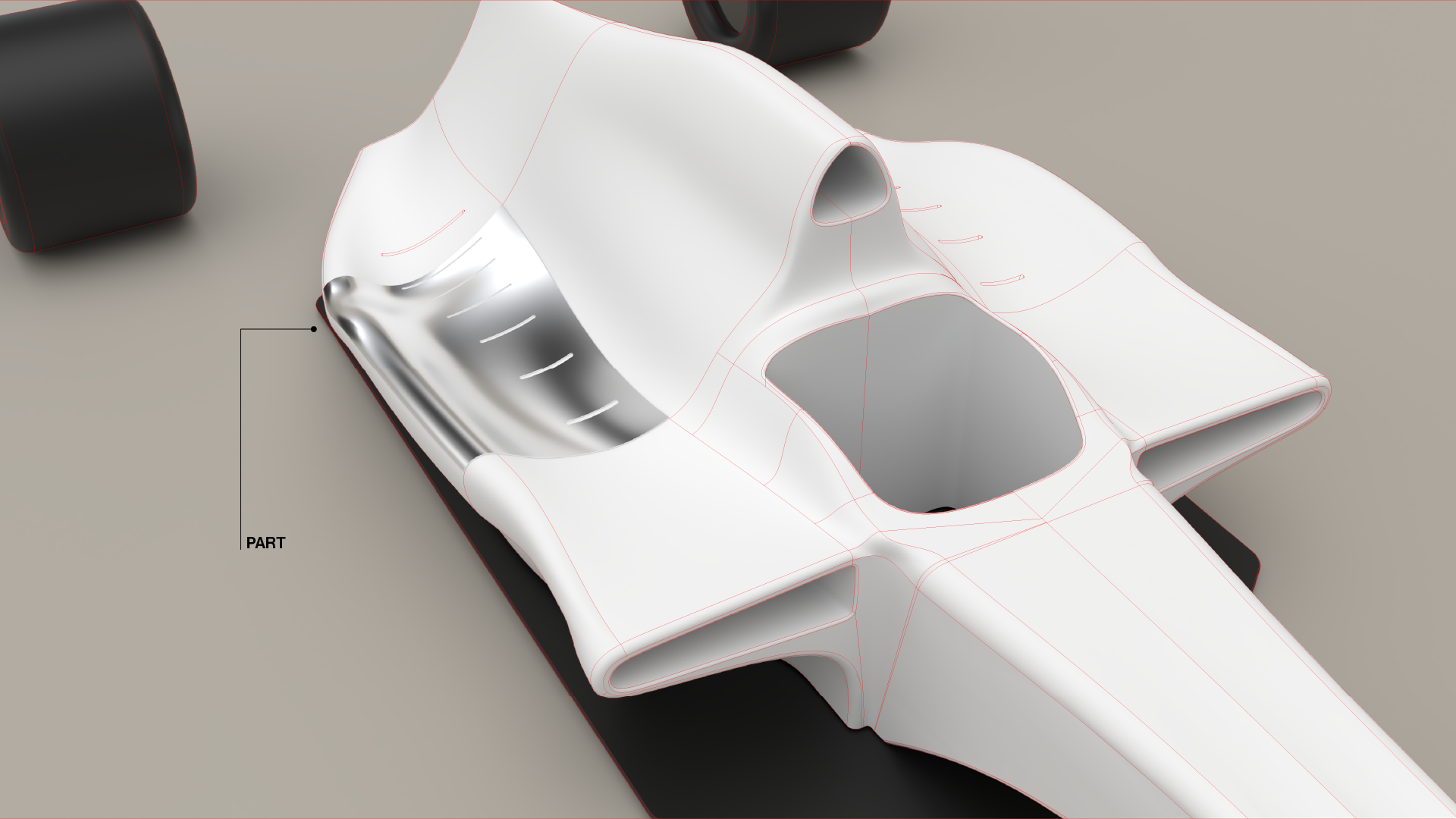
Example part in assembly context
Forming surfaces are often part of larger assemblies. To process parts for Roboforming, the desired geometries must be extracted and provided as a single surface (no thickness) in a Parasolid format according to our export instructions. Any edges to be trimmed, both the part boundary and any internal cutouts, must be maintained as naked edges.
Orientation and Draft Angle
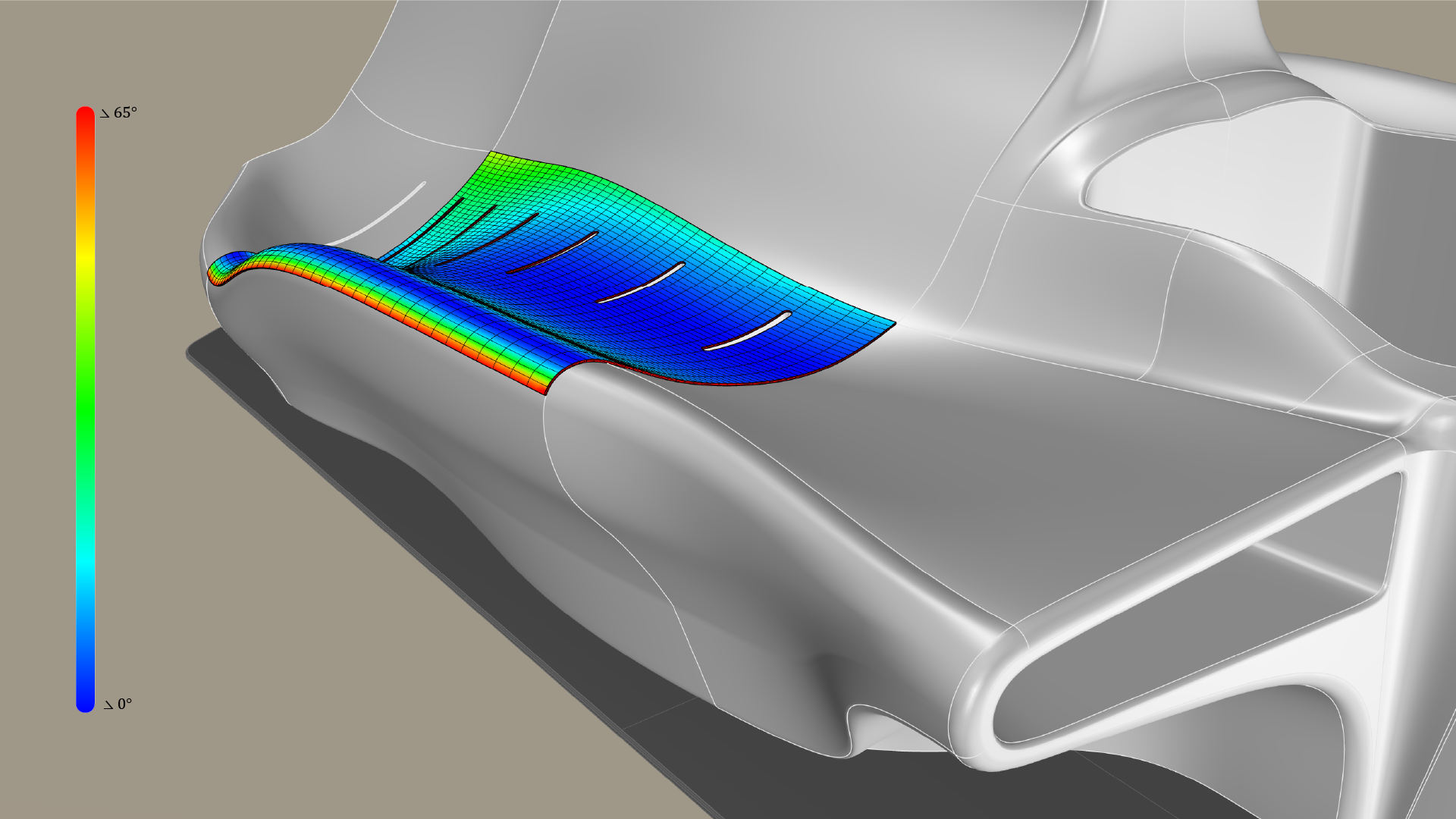
Example part in assembly context
Wherever a part is designed, there must exist at least one orientation in which the walls do not exceed an angle of 60° above the horizontal work plane (sheet plane/ XY plane). The part in this example was designed with complex curvature and the in-situ wall angle exceeds 65° (shown along the gradient as red). Still they can be oriented such that the walls are less than 60°, similar to orienting a part for a 3-axis additve/subtractive process. It may even be useful to flip the part to allow for the "skirt" geometry, analagous to AM support material, geometry connecting the part to the unformed sheet (discussed below).
Note that the example above uses 60° as the max wall angle as a typical case. See the table above for max wall angle guidelines for common sheet stocks.
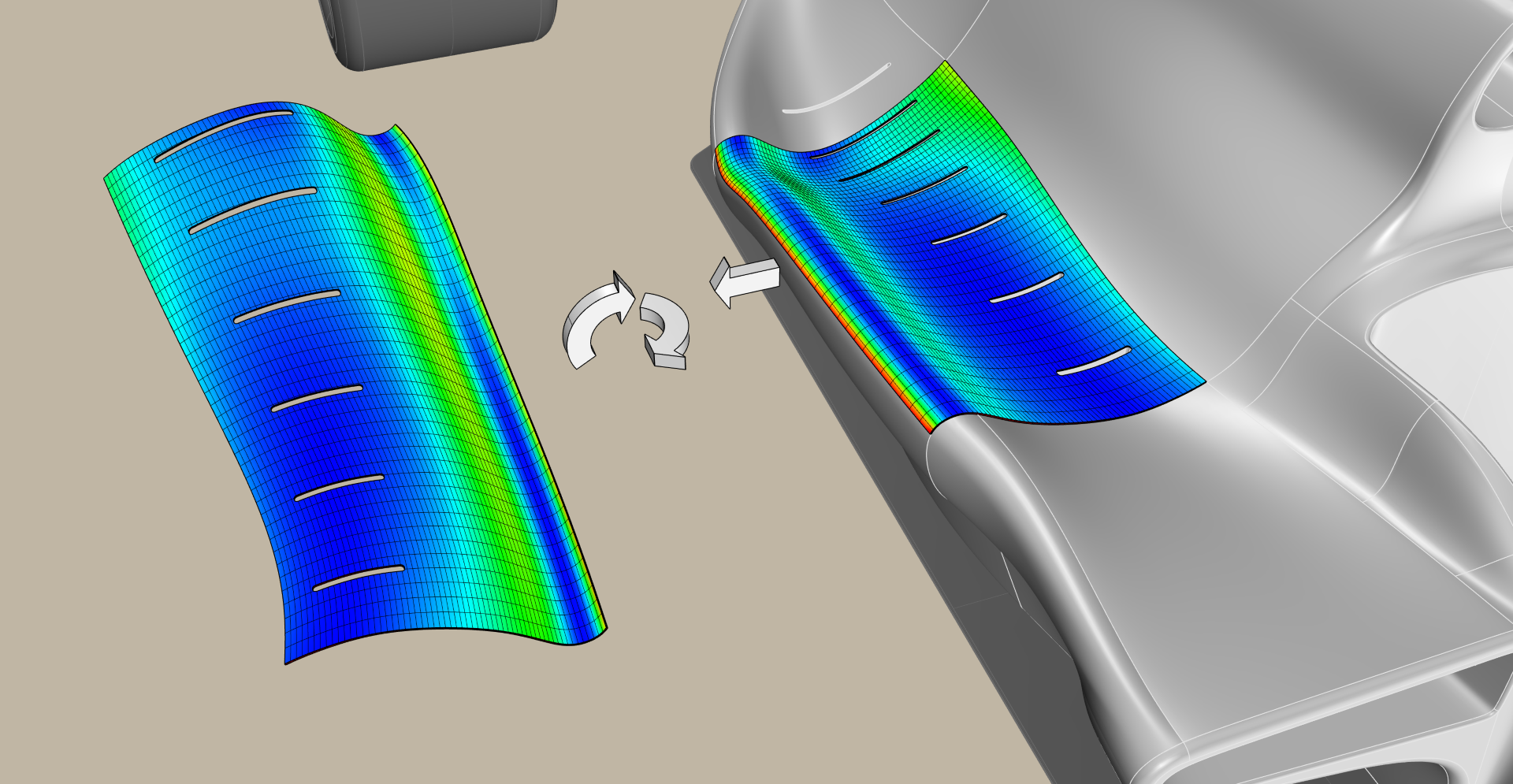
Example part oriented for forming
Sheet Sizing
Standard sheets are 60" wide, and can be up to 144" long to fit on frames custom designed for Roboforming. With space for clamping and tool clearance, about 5" is required on all sides.
A typical part orientation and fitting is shown here with a 60" x 60" sheet stock. The part and skirt sit squarely in the center to minimize assymetric boundary conditions.
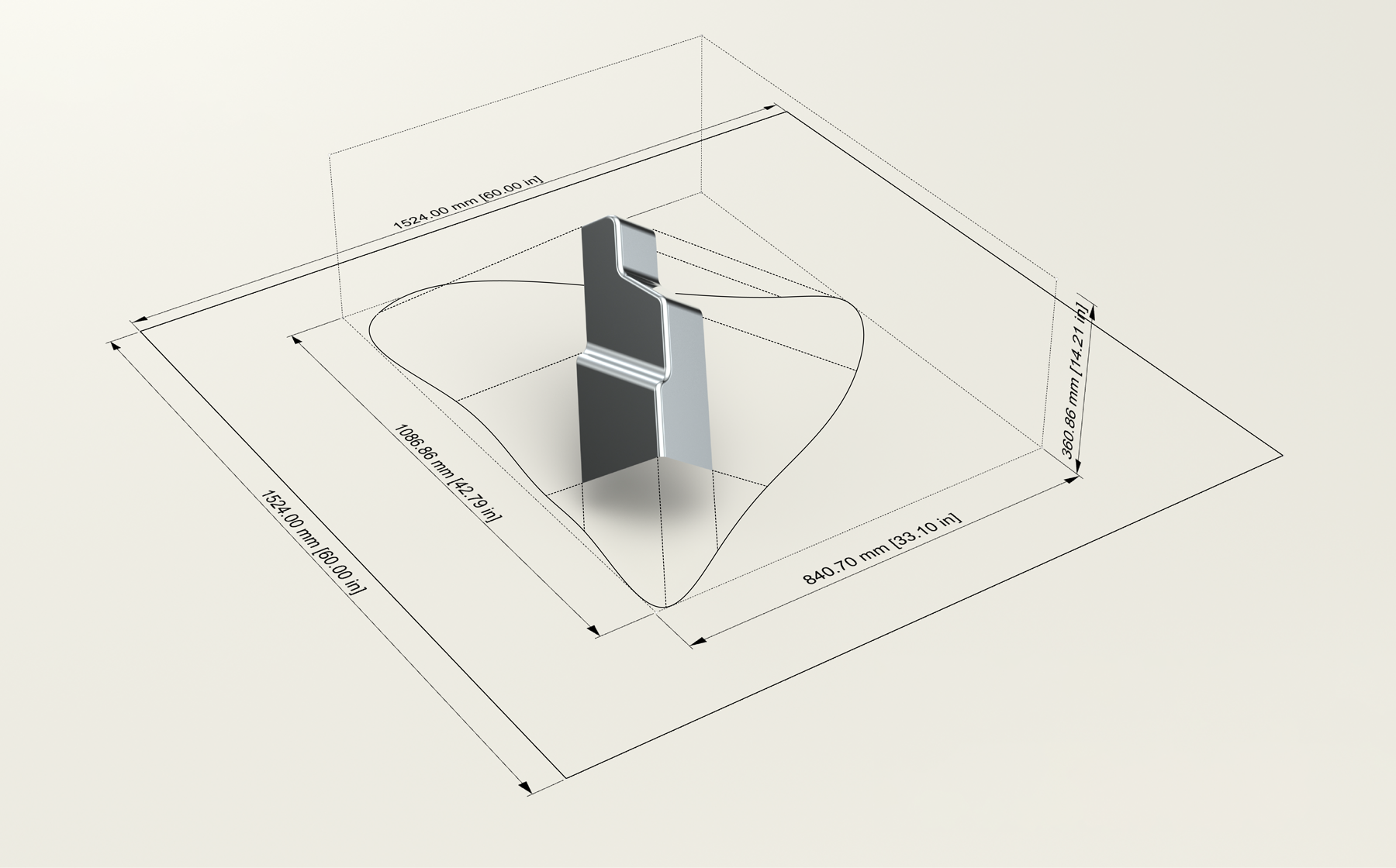
Forming surface sketch including skirt (wireframe)
Part Sizing
A general bounding volume for parts is 135" x 50" x 50", including the "skirt," the additional sheet necessary to connect the edges of the part to the unformed sheet plane.
A more specific bounding box estimate would be the outline of the oriented part with its edges projected tangentially towards the plane, as shown here. There are more ways to fit and orient parts for forming, but this is a safe starting point.
Edge Condition
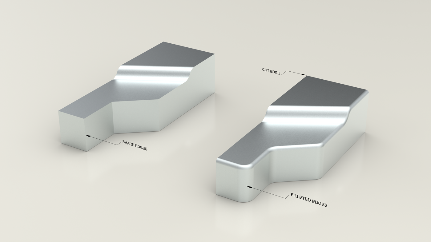
Left, non-formable edges and right, appropriatedly filleted edges
Any geometry to be formed must be free of sharp edges. The ball-shaped end effectors used in roboforming have several different sizes with a surface finish - feature size trade space, but none are infinitely sharp.
By contrast, the trimmed (cut) edges of the part may have sharp corners, provided they are external corners. Robotic milling uses high speed endmills in standard sizes, so internal corner radii should obey ~1/16" at minimum.
Common Errors
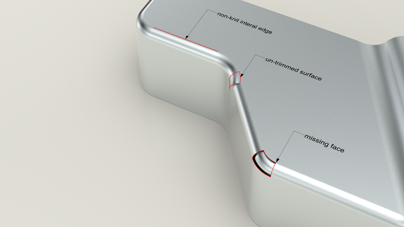
Example part with commonly found CAD errors
Knit Edges, Untrimmed Surfaces, Missing Faces
With complex surface designs, there are several common build/re-build errors. Geometry near the scale of model tolerances can result in surfaces trimming improperly, leaving slivers hanging off of an edge, which must be trimmed by another method. Surfaces built and then joined can fall just outside the model tolerance, leaving small gaps which must be closed. Joining many surfaces into solids or polysurfaces can sometimes leave out surfaces, resulting in a missing face. Edges that are extremely close but not identical may leave small gaps or "un-knit"/"naked" edges in the midle of the surface.
In order to properly slice and path plan for roboforming, a surface must have no non-manifold edges, only gaps which are intended to be cut out, and loops of naked edges signifying the part edge and internal cut-outs.
File Export Guidelines
The Application Engineer assigned to your project will review parts and do any final prep in Solidworks. To ensure a smooth handoff, please export your prepared parts as a Parasolid (.x_t or .x_b).
If you're designing in software without direct Parasolid support, let us know before beginning a project so that we can recommend the best conversion.